
Polariscopes are simple devices used to characterize minerals or look for stress in glass and plastic. Below is a polariscope simulator with changeable polarization items. The round polarizer and up to 2 items can be rotated by clicking and dragging, or by changing the relevant angle value below. Item selection and magnitude of the polarization properties can also be changed below.
- linear birefringence: phase difference between two linear polarizations [magnitude units = nm]
- linear diattenuation: polarization-dependent absorption [magnitude units = unitless]
- circular birefringence: phase difference of right and left circular polarizations [magnitude units = nm]
- wedge birefringence: linear birefringence with increasing birefringence magnitude [magnitude units = nm]
- scattering: random polarization (example: a piece of paper)
The polariscope consists of two polarizers with one or more transparent items placed between the polarizers. In this model, the first polarizer is fixed in place and transmits only 0° polarized light. In other words, the light starts horizontally polarized. Up to 2 items may be included in the polariscope simulator: a large item and a small item, which are encountered in that order. Lastly, light encounters a circular-shaped polarizer whose angle can be changed.
Microscope Tint Plate
A tint plate is typically a wedge made of quartz. In normal viewing, it is completely transparent. However, viewing in a polariscope produces vibrant colors.
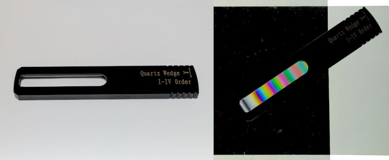
Specific colors are created by linear birefringence and depend on birefringence magnitude. For this quartz wedge, birefringence magnitude varies from near 0 on the left side to approximately 2,600 nm on the right side. Its angle is approximately 34°.
It can be seen in the left side of the wedge that small birefringence magnitude has colors that are mostly shades of grey. To test for weak birefringence, a second item with linear birefringence can add or subtract from the wedge birefringence depending if the two birefringent items are aligned parallel or at 90°. You can try this in the simulator by changing the large item to have linear birefringence and rotating it.
Moving the tint plate in and out of the microscope allows different birefringence magnitudes to be tested. By this method, a skilled mineralogist will use a tint plate to estimate birefringence magnitude of an unknown sample.
Polarization Behavior of Materials
Most transparent minerals and crystals have linear birefringence that change color when viewed in a polariscope. Even water ice in the form of a snowflake has measurable linear birefringence due to its hexagonal symmetry. The only minerals which do not have linear birefringence belong to the cubic (isometric) crystal system[1]. An example of a mineral without birefringence is diamond.
Beyond linear birefringence, there are materials which have circular birefringence. Similar to the linear form, circular birefringence will change colors in a polariscope depending on the birefringence magnitude (thickness of material). However, unlike linear birefringence, the angle of a circular birefringent material does not matter. Circular polarization does not have an orientation, only right or left handedness.
Although less commonly encountered in nature, circular birefringence has important applications. For example, some saccharimeters use circular birefringence to quantify sugar content when distilling alcoholic beverages. This is because sugar exhibits right circular birefringence by nature of its molecular structure.
Some materials, such as tourmaline, also exhibit polarization-dependent color, but not because of phase changes from birefringence, but rather amplitude losses from diattenuation. Unlike birefringence, diattenuation color changes are not an inherent property of polarization, and instead depend on other properties, such as impurities. For better understanding diattenuation vs. birefringence, the simulator assumes no color change from diattenuation.

Optical Interference
To fully understand the polariscope simulator, it is necessary to examine the math describing light we observe.
Using Jones matrix notation[2], the electric field vector exiting the polariscope can be computed:
Working right-to-left, the elements are as follows. The vector (1, 0) characterizes horizontal polarized light assumed for the light source. This could be unpolarized sunlight after passing through a horizontal polarizer. Next an arbitrary Jones matrix with elements jxx, jxy, jyx, jyy characterizes the item being observed. Lastly, the matrix with sines and cosines characterizes the top polarizer which only transmits light at an angle θpol. The result of all this is an electric field vector (Ex, Ey) describing light exiting the polariscope.
Our eyes cannot directly see electric fields. Instead we see irradiance () which is proportional to the magnitude-squared of the electric field vector.
Here 'c' is the speed of light in vacuum, and 'ε' is the average dielectric constant of the material. Next, the complex values jxx and jyx can each be written in polar form assuming a real-valued amplitude (a) and phase (φ).
This allows the magnitude to be expanded.
If we now define and then the observed polariscope irradiance matches the familiar equation for two-wave interference.
As a result, birefringence colors observed in a polariscope are equivalent to colors observed in other systems with two-wave interference. For more details why these famous colors[3] appear, see my related page about soap bubble colors.
Pedantic details
To keep a reasonable update rate, the simulator samples the visible spectrum (395nm to 710nm) every 5 nm when generating each color. For wedge birefringence, 50 values of birefringence magnitude define the displayed color gradients.
For best possible accuracy, simulated colors follow the sRGB specification[4] which is the default color space for web graphics[5]. The sRGB specification assumes D65 standard illumination[6] and color observer characterized in 1931 for a 2 degree field of view[7].
Image of the tint plate was captured with a low-cost LED light pad with unknown color temperature, and was taken by a mobile device with unknown color enhancements. Although the image background was adjusted to reduce distracting reflections, no other adjustments were performed. Detailed color information in the tint plate image should not be relied upon for scientific accuracy.
Simulator calculations assume the decreasing phase convention (). Right-circular polarization is defined by the Jones vector (1,) whose time-varying electric field rotates clockwise when viewed opposite the light propagation direction.
Math equations may not be optimally displayed if no math font is installed. This is most likely to occur with some mobile devices or older desktop operating systems. For optimal display, please install any of the following fonts: Latin Modern Math, STIX Two Math, Cambria Math.
References
- "Optical Mineralogy: Principles and Practice", Gribble and Hall, Chapman & Hall, 1993. https://doi.org/10.1007/978-1-4615-9692-9
- written as an 8-part series spanning 15 years, R. Clark Jones developed what are now described as Jones vectors and Jones matrices. The first paper in that series is: "A New Calculus For the Treatment of Optical Systems", Journal of the Optical Society of America, vol.31, 1941, pp.488-493. https://doi.org/10.1364/JOSA.31.000488
- The Michel-Lévy birefringence chart was created by A. Michel-Lévy, "Les Minéraux des Roches", Librairie Polytechnique, Baudry et cie éditeurs (Paris), 1888, planche coloriée, 'Tableau des biréfringences'.
- "Multimedia systems and equipment - Colour measurement and management - Part 2-1: Colour management - Default RGB colour space - sRGB", IEC 61966-2-1:1999, International Electrotechnical Commission, https://webstore.iec.ch/en/publication/6169
- "All RGB colors are specified in the sRGB color space..." is a quote from "CSS Color Module Level 3", section 4.2.1, W3C Recommendation, 2022. https://www.w3.org/TR/css-color-3/#numerical, retrieved 2026-05-30.
- "CIE standard illuminant D65", International Commission on Illumination (CIE), Vienna, 2019, https://doi.org/10.25039/CIE.DS.hjfjmt59.
- "Colour-matching functions of CIE 1931 standard colorimetric observer", International Commission on Illumination (CIE), Vienna, 2019, https://doi.org/10.25039/CIE.DS.xvudnb9b.